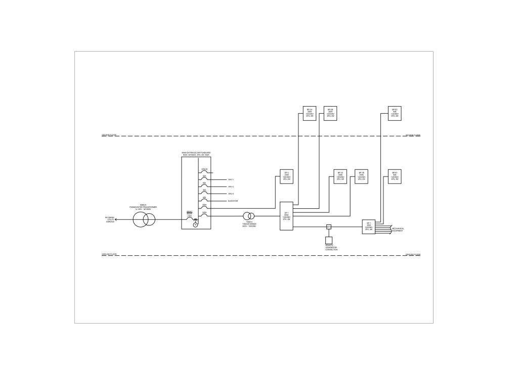
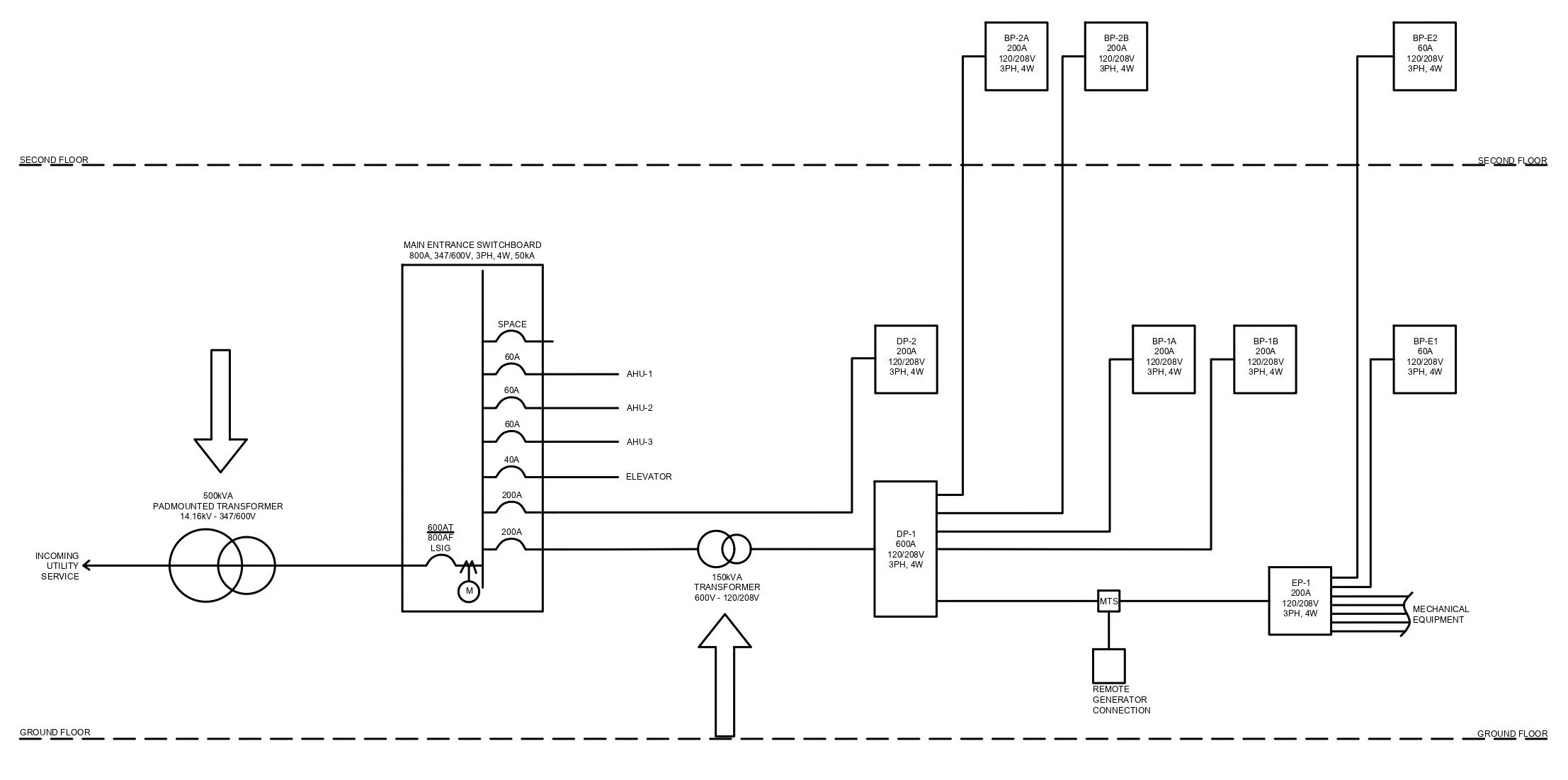
Single line diagrams (SLDs), also known as one-line diagrams, are crucial visual tools in the world of electrical engineering. They are like a map of an electrical power system that shows all the major components and how they’re connected. It’s a fundamental tool for understanding the electrical power system.
What is a Single Line Diagram?
In a single line diagram, you’ll see symbols that represent things like generators, transformers, circuit breakers, and switches. The symbols are connected by lines that represent the conductors that carry the power through the system. These diagrams are used by engineers and technicians to design, build, and maintain power systems. The SLD provides a concise and practical alternative to showing all he conductors as a single line, and the components of the system as standardized electrical symbols.
The fundamental principle of an SLD is to offer a bird’s-eye view of how power is distributed from the point of utility supply to the end consumer. This includes showing the path of electrical flow through transformers, circuit breakers, panels, switchgears, and other electrical equipment.
Significance of Single Line Diagrams
SLDs are crucial in both the design and maintenance phases of an electrical building system. They provide a clear and simplified view of the system, showing the flow of power from the utility source to the loads, and the interactions between different components. They’re used for a variety of purposes, such as system planning, troubleshooting, and maintenance.
Here are some of the main uses of SLDs:
-
System Design: During the design phase of a building’s electrical system, SLDs help in determining the layout of electrical components, sizing equipment, establishing the system’s operational parameters, and planning for potential future expansion.
-
Maintenance and Troubleshooting: For maintenance personnel, SLDs provide an invaluable reference tool. They allow engineers to trace the source of electrical faults, plan repairs, and perform system upgrades.
-
Safety Planning: SLDs are also used to plan safety measures, such as the placement of circuit breakers and the routing of emergency power supply.
-
Compliance and Documentation: SLDs serve as an essential record of the electrical system’s layout, ensuring the building’s compliance with electrical codes and standards. They also help in providing information to inspectors, insurers, and potential buyers.
Key Components of Single Line Diagrams
SLDs use standardized symbols to represent different electrical components. Here are some of the key elements commonly found in SLDs:
Generators/Power Supply: This symbol represents the source of electrical power, which could be a utility supply, emergency generator, or a renewable energy source.
Transformers: Transformers are used to step up or step down the voltage in the system. They are usually depicted as two different sized circles or a by a rectangle with the text “TX” inside of it.
Switchgears and Circuit Breakers: These devices control, protect, and isolate electrical equipment.
Loads: These are the end users of electricity, such as lights, HVAC systems, and appliances. They are usually shown as a circle or square, with a label indicating their nature.
Conductors: These are the connecting points between all electrical components. They are the line in the single line diagram that represent the conductors and conduits needed at every point in the distribution of the electrical system.
We use modelling software to create and modify these diagrams, some specialized software can also perform calculations like voltage drop and short circuit analysis to make sure the system is safe and reliable.
Overall, single line diagrams are a critical tool for us to understand and design electrical power systems and are are a powerful tool in the electrical engineer’s toolkit. They help us plan and design new power systems, troubleshoot problems, and schedule maintenance activities. So, if you’re ever curious about how an electrical power system works, take a look at a single line diagram. Refer to our calculators to help design your building’s distribution system.


